|Inspection | Rotor/Dist Gap | Point Gap | Timing | Primary Circuit | Secondary Circuit | Tech Tips by Tom Endy |
Special thanks to Tom Endy for his Tech Tips and Tom Wesenberg for his tips on checking Coil Polarity and Installing the Condenser properly.
After reading this page:
Visit the fordgarage.com
for historical and detailed information.
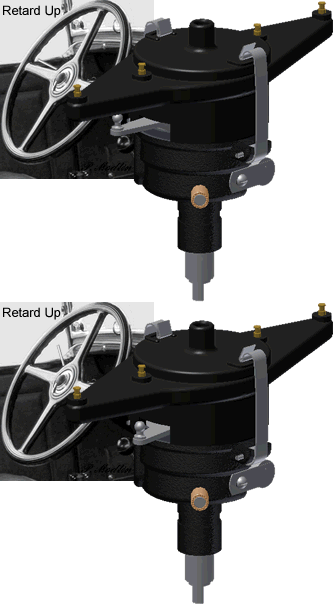
Inspection: The fix:
For the 29-31 two tooth steering, loosen both steering column clamps.
One is inside the cab and the other is under the hood. Rotate the steering
column until the arm functions properly. Tighten the clamps. |
 |
|
|
|
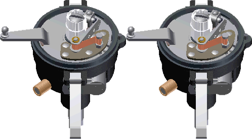
Inspect the Distributor Shaft. The Distributor Shaft should not rock back and forth. If it does rock, it is time to replace the bushings.
|
 |
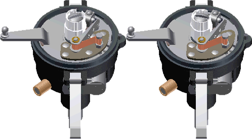 |
Slight rotational play is ok.
|
|
|
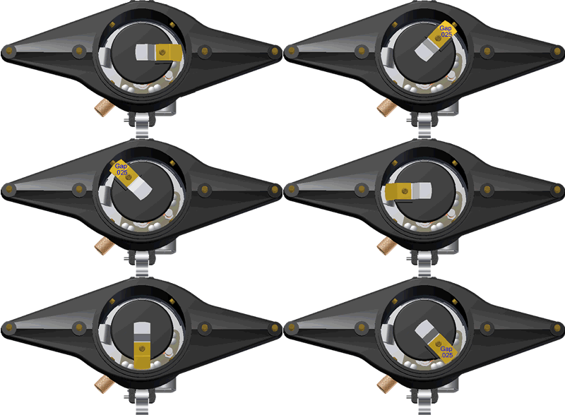
Put on parking brake, place gear shift lever in neutral position, and use the Hand Crank to rotate the rotor. Check the rotor at all four distributor contact points. The gap should be .025
The fix: Bend the Rotor and/or file the contacts on the Distributor Housing. |
 |
|
|
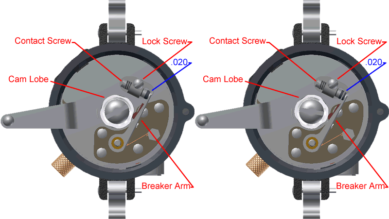
| Setting Point Gap To adjust points proceed as follows: 1. Lift off distributor cap, rotor, and body. Turn engine over slowly with hand crank until breaker arm rests on one of the lobes of the cam with the breaker points fully opened. 2. Loosen lock screw and turn the contact screw until the gap is between .018 and .022”. A standard thickness gage is used to obtain this measurement. When correct adjustment is obtained, tighten the lock screw. After tightening the lock screw, again check the gap to make sure the adjustment was not altered when the lock screw was tightened. 3. Replace distributor body, rotor and cap or proceed to ignition timing. |
 |
Ignition Timing: |
|
7. Screw out timing pin located in timing gear cover and insert opposite end of pin into opening. 8. Find Top Dead Center. With the hand crank, turn the engine over slowly, at the same time pressing in firmly on the timing pin. When piston # 1 reaches the end of the stroke (top), the timing pin will slip into a small recess in the cam gear. Tip: If the engine had been running recently, the timing pin should drop into the recess when the rotor is about to line up with contact #1 on the distributor cap. |
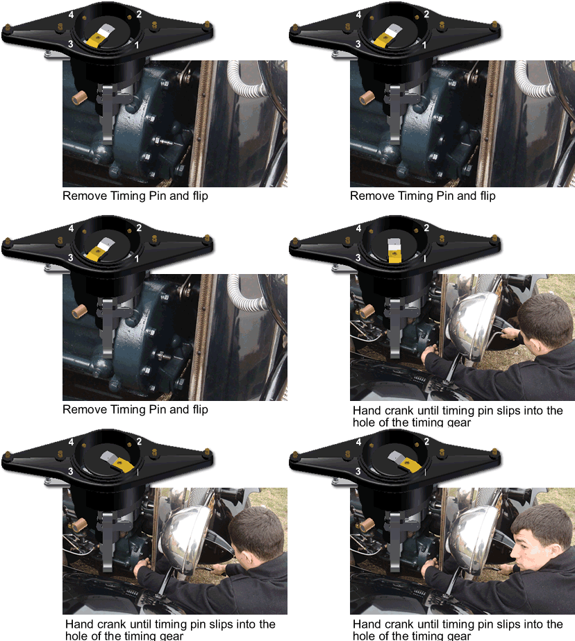 |
Note: While hand cranking to find the timing mark mark, occasionally pause to relieve the compression pressure. Note: If the timing mark is missed it is two revolutions, with the hand crank to return to the previous point. Note: By removing Plug # 1 and shining a small flash light into the hole, it is possible to see the top of the piston when you are at Top Dead Center. Note: By removing all the plugs, the compression is eliminated and the engine is easier to hand crank. |
|
9.Remove the cap and rotor. Loosen cam locking screw until the cam can be turned. Note: A cam wrench can be purchased from one of the Model A venders, makes the job easier. 10. Replace rotor and/or use the cam wrench to turn and line up the notch in the cam with the No1 contact point on distributor head. 11. Remove rotor and/or wrench from cam and using your fingers slightly turn the cam in a counter clockwise direction, until the breaker points are fully opened. 12.Slowly turn the cam back in a clockwise direction until the points just close. |
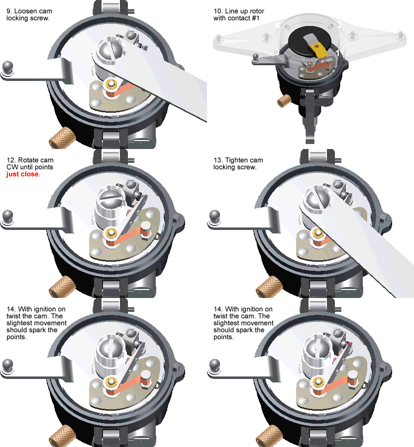 |
13. Lock the cam by securely tightening the cam locking screw. This method removes the backlash in the distributor shaft from affecting the timing. 14.Turn on the ignition and with your fingers twist the cam counter clockwise. With the slightest movement the points should spark. If it does not spark retime. Final check with the ignition on pull the spark advance lever down one or two notches and listen and/or have someone watch for a spark from the points. If the lever moves more then three notches retime. Replace timing pin and put away crank Oil the distributor and Apply Vaseline to the cam. 15. Reassemble distributor housing, rotor, and cap |
|
|
Model A's are positive ground. The Model A frame acts as the positive ground wire from the battery
|
|
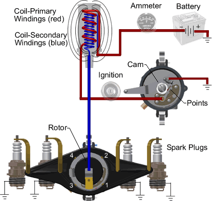
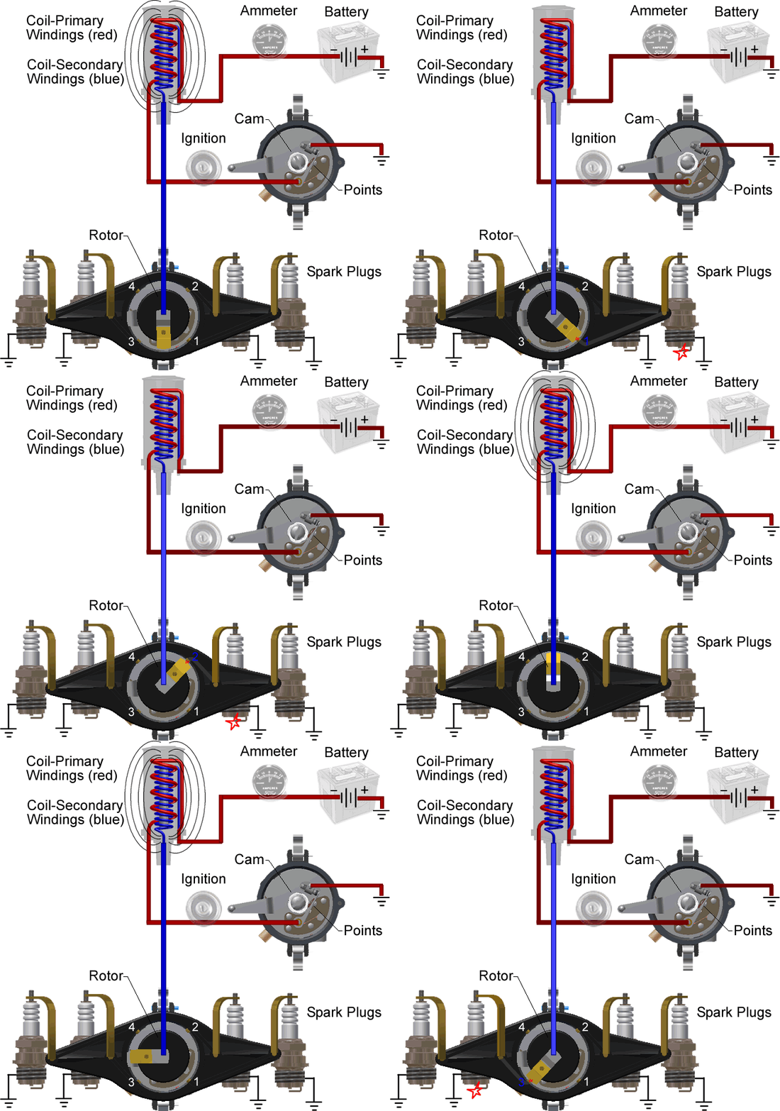
The Primary Circuit.
|
 |
|
The Secondary Circuit is the high voltage side of the ignition system. The voltage is generated when the magnetic field collapses in the primary windings.
|
|
Primary and Secondary System The ignition switch allows the driver to turn the system on and off. Turning the key to the on position closes the circuit and allows current to flow. As current flows around the primary coil, a magnetic field is created. The strength of the magnetic field is determined by how long the points are closed. The points act as a mechanical switch that is controlled by the distributor's cam. When the points open, the circuit is broken; this instantly collapses the magnetic field and induces a high voltage into the secondary windings. The voltage is so intense that in its path to ground, it is able to ionize the air gap of the spark plug, thus igniting the fuel air mixture in the combustion chamber. |
 |
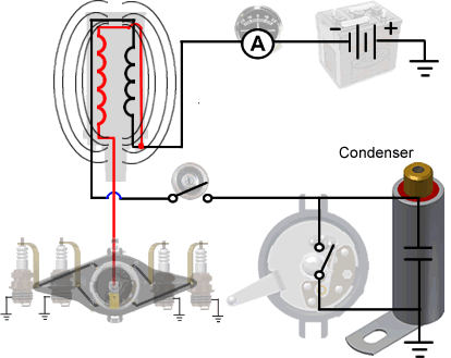
How The Condenser Works The function of a condenser is to provide a false ground. When the points open and the magnetic field collapses in the coil. A high voltage is created in both the primary and secondary windings. The voltage in the secondary windings heads towards the spark plugs to ignite the fuel; while the new induced voltage in the Primary windings searches for ground. The voltage created by the collapsing of the magnetic field in the primary coil is strong enough to jump the gap between the points in the distributor as they open, but instead, the current is attracted to the condenser, where it is collected and stored to assist in the next cycle of creating a magnetic field in the Primary Coil. |
 |
|
| Note: At one time the condenser was considered the weak link in the system and failed often. Today's reproduction condensers do not fail like their predecessors and are quite reliable. | ||
Tom
Wesenberg Tip: |
||
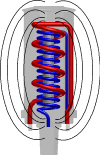
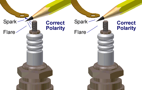
How The Coil Works The coil itself does not care which way it is hooked up, it will be just as efficient either way. On the other hand the spark plugs do care. They prefer the center electrode to be negative and the end electrode to be positive. The reason is electrons like to jump from a cold surface to a hot surface and the center electrode of a spark plug is hotter than the end electrode. By correctly establishing the coil’s polarity the voltage required to jump the spark plug gap is 15 to 30 percent stronger which may or may not be evident on the performance of your ‘A’ depending on the condition of the ignition components. Oddly enough the large amount of voltage created by the coil is not affected, positively or negatively, by the mere 6 volts (or 12) of the battery. Therefore; positive ground or negative ground of the battery is not relevant. |
 |
|
Tom
Wesenberg Tip: If the flare is on the plug wire side. Switch the two wires on the coil. |
 |
|
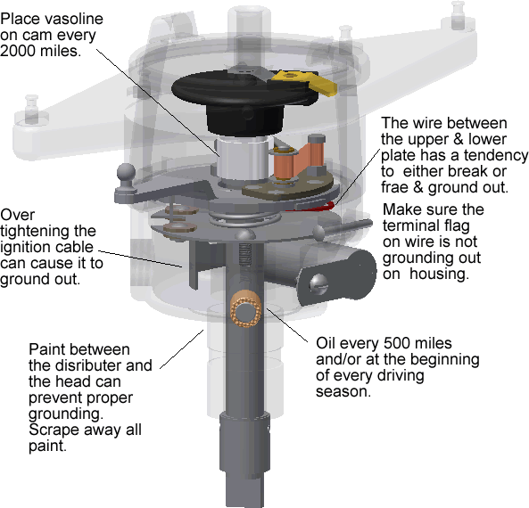 |
||
| Restoration Tips by Tom Endy | ||
Distributor
Techniques |
||
| Distributor
Roadside Seminar On any long club tour sooner or later one of the Model A's will pull over to the side of the road and up will come the hood. The first component to be attacked is the distributor, and it is probably the most likely source of the problem.. |
||
Model
A Ford Ignition Diagnostic |
||
| The
Ammeter The ammeter in a Model A Ford can be a very useful tool in a variety of situations that will signal to the driver the car’s electrical status. |
||
For a complete listing of Tom Endy's Tech Articles, Please visit: http://www.ocmafc.org/
Inspection | Rotor/Dist Gap | Point Gap | Timing | Primary Circuit | Secondary Circuit | Tech Tips by Tom Endy | |
||
